What is strain gage measuring ?
Measurements by means of strain gages are in the world of 1/1,000,000
It is stated in the last paragraph that one can easily measure with strain a variation of physical amount in terms of the “length” in the level of 1/1,000,000. We can say it may be extremely difficult with an ordinary measuring system to measure the length of for example 100 meters in the exactitude of 0.1mm. In the measurement with strain gages, however, a resistance variation of ΔR in the formula of ΔL / L ∝ ΔR / R can seize the world of 1/1,000,000 through the Wheatstone Bridge because the resistance wire in the length of “0.3 to 5mm”is receiving an external force in the strain gages.Purpose of measurements by means of strain gages
Although the strain gage is usually detecting the local linear variation in ΔL, it may be a general practice to replace the amount of variation into the stress, external force, pressure and so on which are the physical amounts led from the above-mentioned amount of linear variation. In view of the fact that almost all strain gages being put on sale in the market are self-temperature compensated ones, it is expected to divert these strain gages into the use including the assessment of unknown linear expansion coefficients of a variety of materials.Terminology and expressions wothy to know of in relation with strain gages
- Definition of strain:ε=ΔL/L , Gage Factor:ΔR/R=K*ε
- Expression of relations of perpendicular stress and strain:σ=E*ε
- Expression of relations of shearing stress and shearing strain:τ=G*γ
- Calculation formula of perpendicular stress:σ=P/A
- Calculation formula of bending stress:σ=M/Z=6M/bh^2 (Z :modulus of section)
- Calculation formula of shearing stress by the torsional moment of the round bar :τ=T/Zp= (Zp:polar modulus of section)
- ・Circular cross-section “Zp”):π*d^3/16
- ・Hollow circular cross-section “Zp”:π*(d2^4-d1^4)/16*d2)
- Expression of relations of Young’s modulus “E” and modulus of rigidity “G”:G=E/2(1+ν)
- Strain Gage Factor “K”:The product of strain and the quotient of change in strain gage resistance and unstrained resistance of strain gage.
- Poisson’s ratio “ν”:The ratio of transverse contraction strain”εb” to longitudinal extension strain”ε” in the direction of stretching force.
- Perpendicular stress”σ”:Expression of the internal distribution of force per unit area, σ = F/A, it’s called engineering stress or nominal stress.
- Elastic limit / Yield point:Maximum stress in the linear region of stress-strain curve.
- Young’s modulus / Modulus of elasticity”E”:The constant ratio of tensile stress”σ” to tensile strain”ε”, within the elastic limit.
- Modulus of rigidity / Modulus of trasverse elasticity”G”:The constant ratio of shearing stress”τ” to shearing strain”γ”, within the elastic limit.
Self-temperature compensated strain gages
When the resistance value of a strain gage, one of the resistance elements, has made a relative change per one degree C, this change can be expressed by the equation of ΔR/R=α+K(βs-βg). Therefore, it might be concluded that any effects from the temperature change may be negated if an equation of 0=α+K(βs-βg) can be brought into existence. In these circumstances, because of the fact that the resistance temperature coefficient “α” of the strain gage material of ADVANCE (Cu54, Ni45, Mn1) can be controlled through the thermal treatment applied to this material, it can finally come into a conclusion that one can produce a strain gage which is less in an “apparent strain” and which can match with the linear expansion factor of the materials to be measured. For your information, strain gages being generally on sale are principally self temperature compensated strain gages whose applicable materials are mild steel, stainless steel and aluminium. α :Temperature coefficient of strain gage resistance materials K:Gage Factor βs:Thermal expansion coefficient of specimen βg:Thermal expansion coefficient of strain gage resistance materialsThermal Output Characteristics(Fig.1 / Sample strain gage : N11-MA-5-120-11)
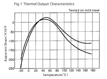 Fig.1 shows the travelling curve of an apparent output of Showa self temperature compensation strain gages caused by the temperature variation extending to these strain gages. There is a considerable variation in the distance between two curves appearing on the graph and this variation in the distance represents the dispersion of outputs of the strain gages. Showa strain gages are compensated to be within ±2μstrain per degree C in the dispersion of output strain curve without employing any dummy gages in the bridge but in the neighbourhood of normal temperatures.
Gage Factor variation temperature(Fig.2 / Sample strain gage : N11-MA-5-120-11)
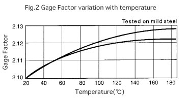 Fig.2 shows a curve representing strain gage sensitivity variation got when the strain gage is bonded on a mild steel specimen to which a constant strain of +1000μstrain at 20℃ is applied and when changing the temperature applied to this strain gage.
Remarks: Movements of this curve include variations of the Young’s modulus of “mild steel”.
Stress-strain curves
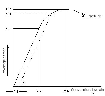 σe:Elastic limit / Yield point
σb:Eltimate stress
*In the case of tensile stress, it’s called “tensile strength”.
εp :Permanennt set
E :Young’s modulus / Modulus of elasticity
Remarks:
Increased load newly in the state that a permanent set was left , and become a new yield point “σ1” with following curve “2~1”, that is to say, A new yield point varies by doing plastic deformation and become a hard-brittle materials.
Simple method for generating equivalent strain by inserting a parallel resistor into one side of the strain gage bridge
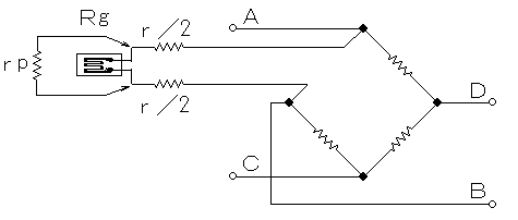 It should be noted that, in case when the length of leadwires of strain gages or that of the cable combining the bridge box with the amplifier is considerably longer than usual, say several 10 meters or longer, effects to be brought about by the sensitivity change due to resistance of longer leadwires may become extremely large that cannot be disregarded. In order to prevent these difficulties from taking place by generating a correct calibration value (an equivalent strain), a parallel resistor (rp) is inserted into one side of the strain gage bridge as shown in the figure given above. For your information, the relations of the gage resistance (Rg) with the calibrated strain (ε) and with the inserted resistor (rp) are shown in the following equations.
Rg/(rp+Rg)=K*ε
rp≒Rg/(K*ε)
Example:
Resistance value to generate CAL-strain / 2,000*10-6 on Bridge resistance / Rg:120Ω, Gage Factor / K:2.00,
rp≒120/(2*2000^-6)=30(kΩ)
Therefore, it should be prepared for outside CAL resistance depending on the strain measurement range.
Calculation of tension and compression stress (1-Gage Method)
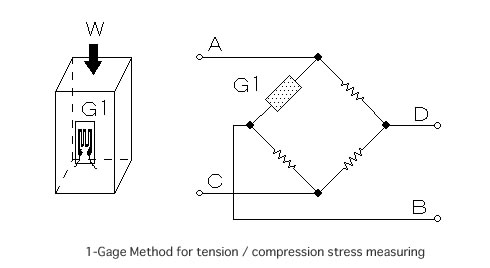 Amounts of stress (σ) and force (W) to be got when one piece of strain gage is bonded, in parallel with the direction of force applied, on the surface of a column which is receiving a uniform force from one certain direction, as shown in the sketch given below, both surfaces are expressed by the following equations:
σ=εo*E
where,
σ :Stress
E:Young’s modulus / Modulus of elasticity
εo:Indicated strain
W=A*σ=A*εo*E
where,
W:Force
A:Cross-section area of column
Calculation of tension and compression stress (2-Gage Method A)
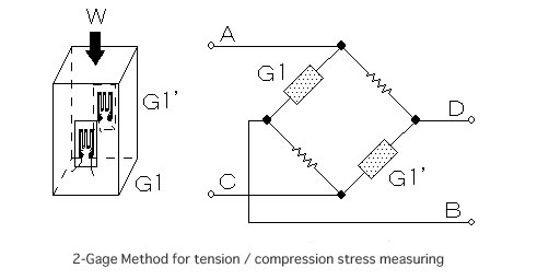 Amounts of stress (σ) and force (W) to be got when 2 pieces of strain gage are bonded on both surfaces of a column in right angle with the direction of force applied as shown in the sketch given below, are expressed by the following equations:
σ=(1/2)*εo*E
W=A*σ=A*(1/2)*εo*E
W=A*σ=A*εo*E
where,
W:Force
A:Cross-section area of column
*Apparent strain by the bending is denied, and it is it with the double output made the average of the axis strain(ε).
Calculation of tension and compression stress (1-Gage Method B)
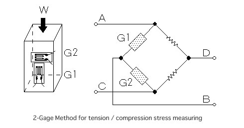 Amounts of stress (σ) and force (W) that the column is suffering when 2 pieces of strain gage are bonded to the direction of forth and to the right angle to the force direction, and when connections are made through the bridge as shown in the sketch given below, are expressed by the following equations:
σ=εo*E/(1+ν)
where,
W=A*σ=A*εo*E/(1+ν)
ν:Poisson’s ratio
*Indicated strain “εo” is output as ε1 and absolute value of ε2(=-νε1).
Calculation of bending stress (1-Gage Method)
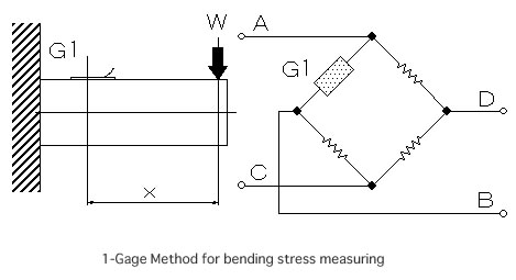 An amount of surface stress (σ) in accordance with bonding positions of the strain gage when one piece of strain gage is bonded on the surface of a beam with a rectangular cross section whose one-side is being locked and the other side is being applied to a force, is expressed by the following equations:
σ=εo*E
M=W*X
where,
X:Distance from the position “W” to the strain gage center.
The surface stress “σ” of the beam due to the moment “M” can be calculated using a next formula.
σ=M/Z
M=Z*εo*E
where,
Z:Modulus of section
Modulus of section of rectangular section is calculated to
Z=b*h^2/6, therefore
W=b*h^2*E*εo/6*X
where,
b:width of beam
h:height of beam
Calculation of bending stress (2-Gage Method)
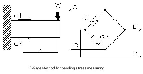 Two strain gages bonded at the contrasting positions of the front and rear surfaces of a beam are equal in their absolute values and the mark of (+) or (-) will come reverse. If the strain gages are bonded on a beam in such a manner that they may be neighboring ones each other, their bending strain will become double and the strains caused by the force to the axial direction may be negated.
In this case, calculated to :
σ=εo*E/2
Calculation of shearing stress
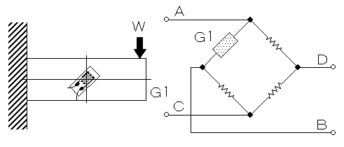 The formula for shearing stress “τ” in a beam is :
τ=F/S
where,
F:Shearing force
S:Cross-section area of beam
In this case, the shearing force of becomes “F = W”, and the shearing stress “τ” due to the cross-section area of the beam can be calculated using a next formula.
τ=W/b*h
where,
b:width of beam
h:height of beam
And, relations of shearing stress “τ” and shearing strain “γ” is :
τ=G*γ
where,
G:Modulus of rigidity, therefore
γ=W/G*b*h
Additionally, shearing stress “τ” and shearing force “W” can be calculated by strain “εo” of the 45 degrees direction because the shearing strain “γ” (rad) is equivalent to double of strain “εo”.
γ=2*εo
τ=2*G*εo
W=2*G*b*h*εo
Calculation of torsional stress
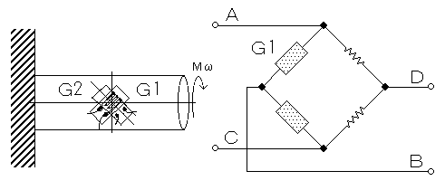 In the axle catching the torsional moment “Mω” like a figure, the shearing stress “τ” becomes greatest at the axis surface; the value is :
τmax=Mω/Zp
where,
Zp:Polar modulus of section
The surface shearing strain “γ” is :
γ=τmax/G=Mω/G*Zp
The indicated strain “εo'” becomes the value of the surface shearing strain “γ = 2*εo” when it’s measured by 2-Gage Method, and the shearing stress “τ” be calculated using a next formula.
τmax=G*εo’
εo’=γ=2*εo
Mω=G*Zp*εo’
