Types and Specifications of Strain Gages
Basic Structure
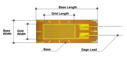
Strain gages are of the stucture, in which a metallic foil film in the thickness of a few microns is glued on a thin electrically insulated sheet (such as polyimide, polyester and so on). This foil film is cut down by photo-etching method in the shape of strain gages which can be made with the negative film masks of the strain gage patterns. These photo-etched strain gage patterns are trimmed to have a standard resistance value satisfying requirements as the strain gages. In addition, for strain gages in general applications, thermal resistance factors of the foil films are controlled to have three categories to match with the thermal elongation factors of 3 major and most popular materials of mild steel/11ppm, stainless steel/16ppm and aluminium alloy/23ppm, for which our strain gages can be self-temperature compensated to minimize temerature effects if specified so when ordering.
Standard Specifications
The following table gives a classification in accordance with the difference in materials of the strain gage grid holding base, namely, one is the polyester FA series and th other is the polyimide MA Series. The FA Series have abundant kinds of types and specifications and therefore are most suitasble for a wide range of strain measurements in general and on the other hand, the MA Series are suitable for strain measurements at medium and high temperatures and for the use as the elements in various industrial or scientific sensors. Model name and rating, dimensions, frequency response and mass (unit: mm)| Specification | FA series | MA series | Unit and Note |
|---|---|---|---|
| Gage Length | 0.3mm to 60mm | 0.3mm to 60mm | standard |
| Gage Resistance | Within ±0.3% of the nominal resistance | Within ±0.3% of the nominal resistance | 120Ω to 1000Ω |
| Foil Material | A : Cu-Ni Alloy | A : Cu-Ni Alloy | |
| Base Material | Polyester | Polyimide | |
| Gage Factor | 2.00 (Nominal) | 2.00 (Nominal) | 1.90 to 2.10 |
| Measurable Strain | 2 to 4% maximum | 2 to 4% maximum | Up to 10% with yielding strain |
| Temperature Range | -30℃ to +80℃ | -30 to +180℃ | |
| Thermal Output | ±2μst/℃(RT to +80℃) | ±2μst/℃(RT to +160℃) ±5μst/℃(+160℃ to higher) | Compensated temperature range |
| Gage Factor Change with Temperature | ±0.015%/℃ | ±0.015%/℃ | Refer to “Tech Information” |
| Fatigue Life | More than 1×10⁵ reversals | More than 1×10⁵ reversals | at ±1000×106 strain |
| Applicable Linear Expansion Coefficient | Common steel Stainless steel Aluminum alloy | Common steel Stainless steel Aluminum alloy | 10.8ppm/℃ 16.2ppm/℃ 23.4ppm/℃ |
Configurations
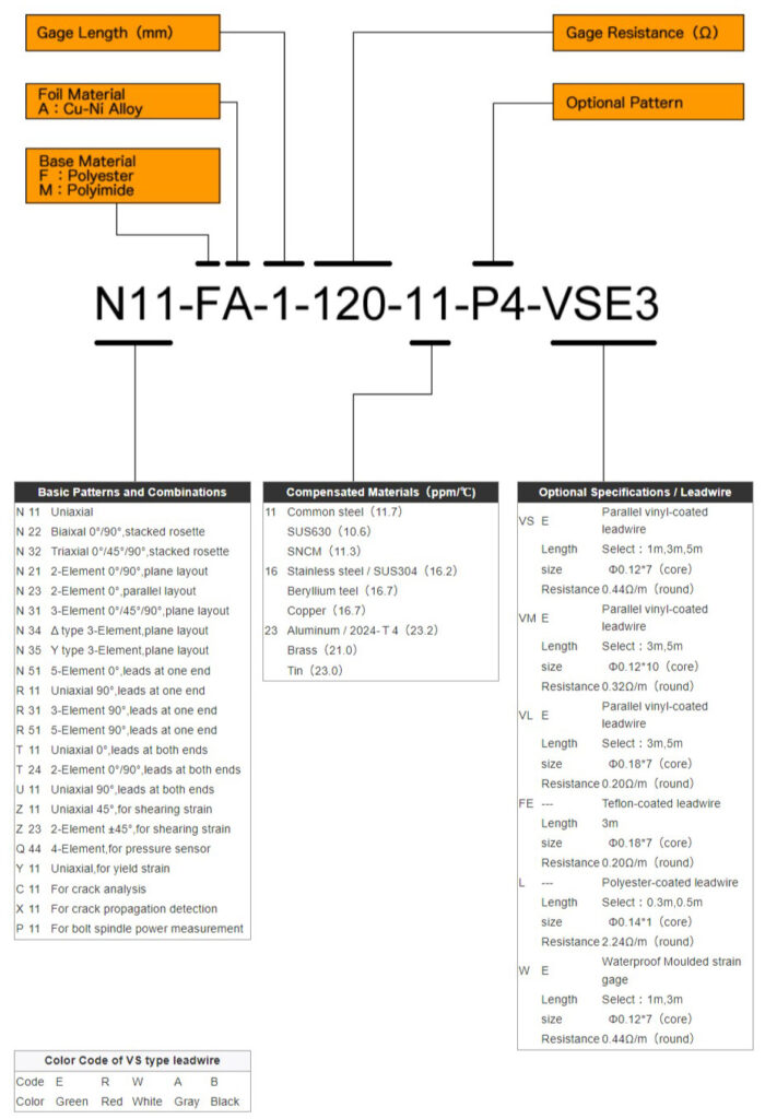
Indication of types of strain gages produced by Showa Measuring Instruments Co., Ltd. is determined in the designation basing on the basic strain gage grid patterns to which some subordinate signs indicating the material of the strain gage grid holding substance, the foil material of the strain gage grid, the length of the strain gage grid, and so on.
- The vinyl color of parallel leadwires of uniaxis strain gages is green (standard) and its symbol is “E”. Vinyl color can sometimes be changed if required.
- The vinyl colors of parallel leadwires of biaxes strain gages are green (Symbol: “E”) and red (Symbol: “R”).
- The vinyl colors of parallel leadwires of triaxes strain gages are green (Symbol: “E”), red (Symbol: “R”) and white (Symbol: “W”).
- The color symbols are not given in the designations of biaxes and triaxes strain gages (VS1, VS3 and so on, for example).
